
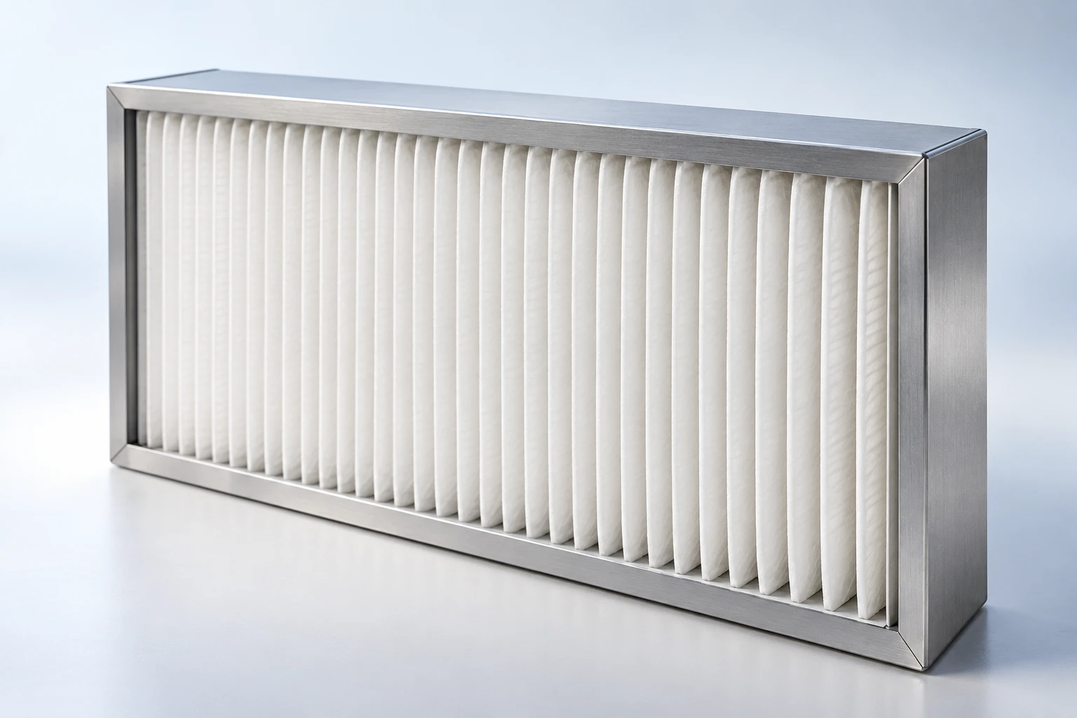
01 · Fine filter
ISO ePM1 ≥ 50 %
In the main module
Air handling in the wall. Room conditions in view. Performance on demand.
Designed for Class Ib operating rooms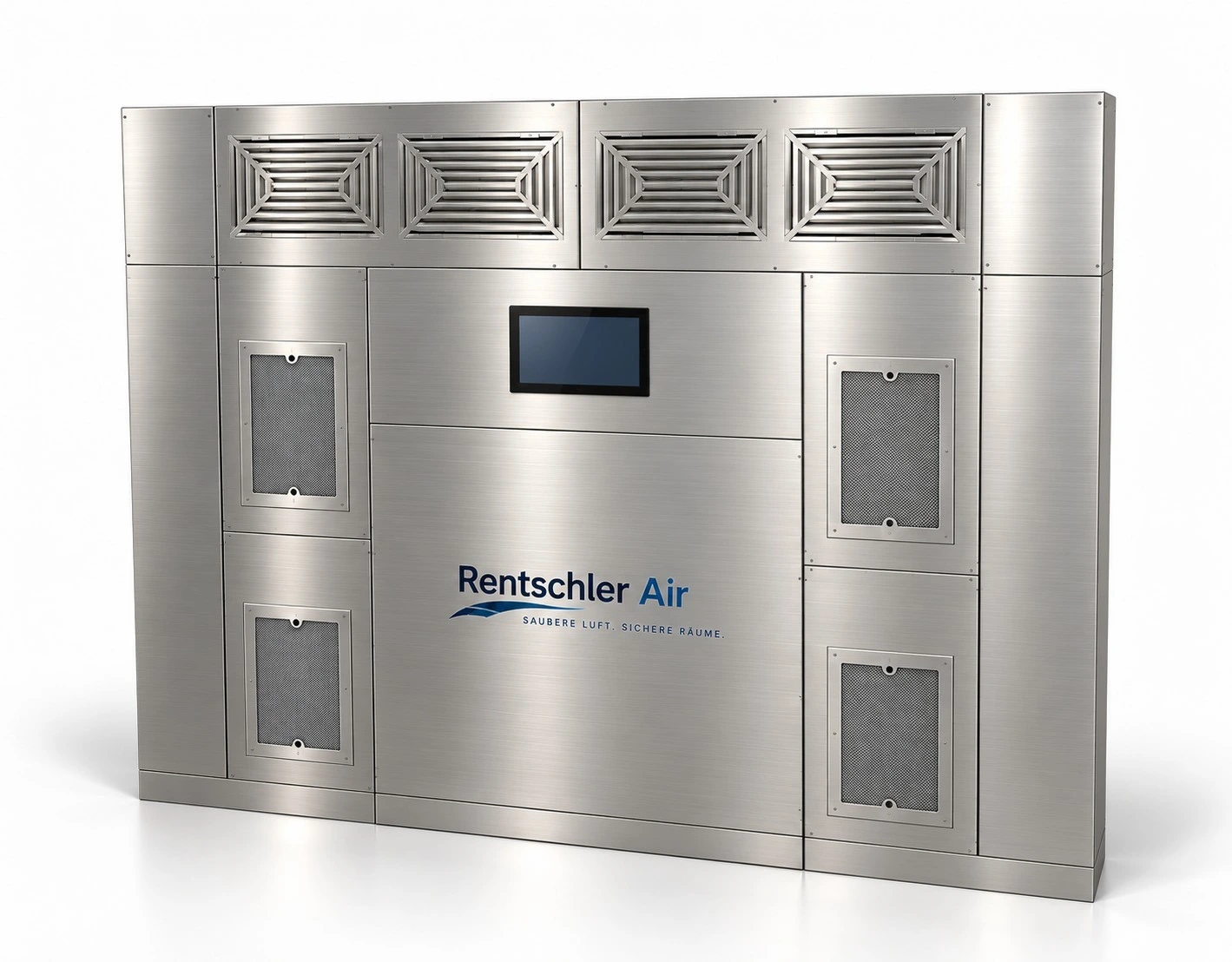
Select a module to see its role in air treatment.
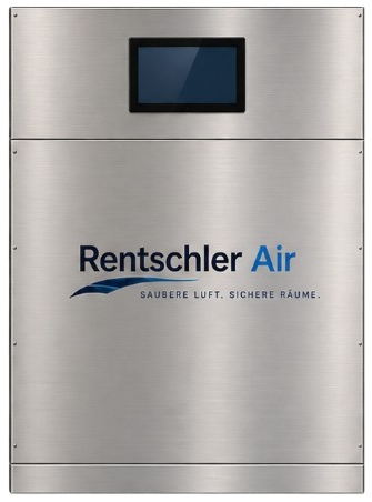
This is where the air is treated: with two fine-filter stages, a heating/cooling coil, droplet eliminator and condensate tray. The controls bring the system together.
ISO ePM1 at least 50% and at least 80%. UV-C integrated in the air path and condensate area.
Select a function to start the product film at the corresponding section.
The film starts only when you choose to play it. You can pause or use the timeline at any time.
Two fine-filter stages in the main module prepare the air. Four final H13 filters are located in the supply air module.
ISO ePM1 ≥ 50 %
In the main module
ISO ePM1 ≥ 80 %
In the main module
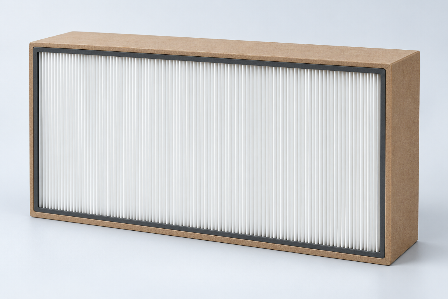
Four HEPA filters
H14 optional
Filter cassettes: symbolic illustrations. The actual configuration is determined for each project.
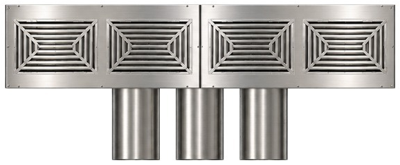
Filter position 1. The four H13 filters are located behind the four outlet sections in the supply air module. This is where the air enters the room after final filtration.
Open filter detail ↗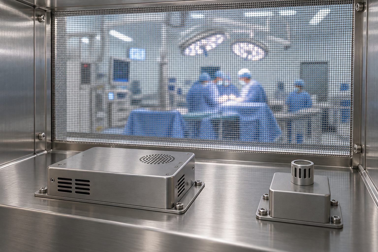 Sensors inside the unit · Principle illustration
Sensors inside the unit continuously monitor particles and capture CO₂ and VOC/mixed-gas signals. The controls use this information to adjust airflow and outdoor air fraction to demand.
Signals are evaluated within the permitted operating range. Minimum airflow rates and hygiene requirements remain decisive.
The brochure specifies particles, CO₂ and VOC/mixed-gas signals. These detect different properties. A VOC signal is neither a CO₂ measurement nor a complete substance analysis. Particle monitoring does not replace project-specific verification.
The controls measure the pressure differential to the adjacent area and adjust the airflow balance when deviations occur.
The illustration shows the intended direction from the clean operating room to the adjacent area.
The pressure differential may temporarily drop. The controls support restoration of the intended positive pressure. The illustration is not airflow verification or a guarantee of pressure maintenance with the door open.
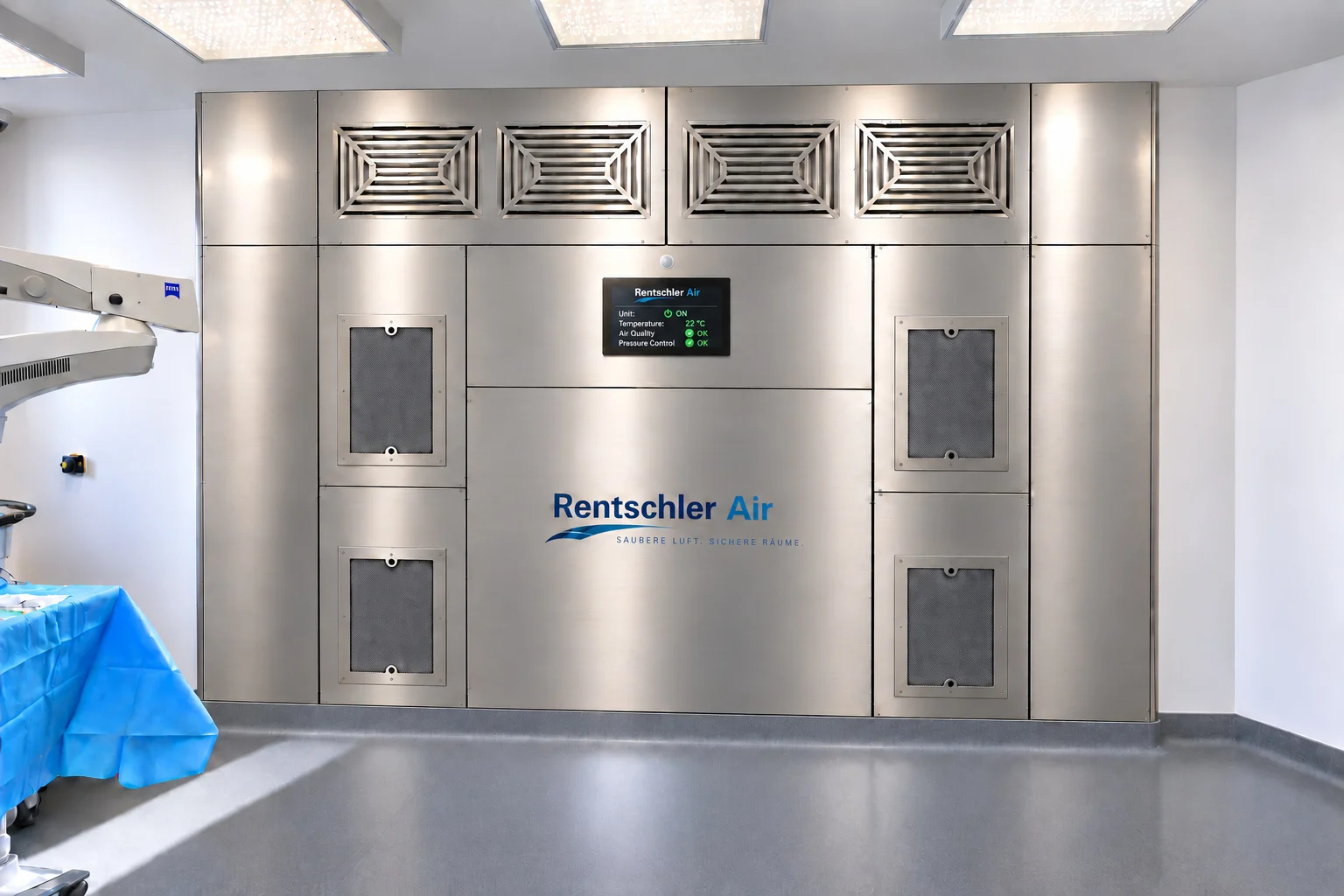
Occupancy informs the operating mode. The system can switch between operation, positive-pressure maintenance and standby within the permitted hygienic limits.
Occupancy information supports demand-controlled operation.
Timings are adjustable. Minimum airflow rates, positive pressure, flushing times and operating permissions remain binding. Occupancy detection alone does not constitute hygienic clearance for surgery.
Indoor unitThe outdoor heat pump, heating/cooling coil and controls match their output to the thermal demand.
Refrigerant lines connect the outdoor heat pump and indoor unit. The illustration shows the principle, not specified line temperatures.
The current brochure specifies a Mitsubishi outdoor unit and a 25 m refrigerant line set. Sizing, line routing and professional commissioning are agreed for each project.
A closed water/glycol circuit transfers energy between exhaust air and incoming outdoor air. Depending on temperatures, heat or cooling energy can be recovered.
Controlled EC fans and demand-based operating modes complete the energy concept.
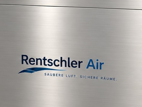
Grade 1.4301 stainless steel, 180-grit visible surfaces and acoustic insulation combine material and construction.

The fixed 100 mm plinth is designed for upturned flooring with a coved junction. The service panels above remain removable. Flooring and corner details are coordinated with the flooring contractor and hygiene planning.
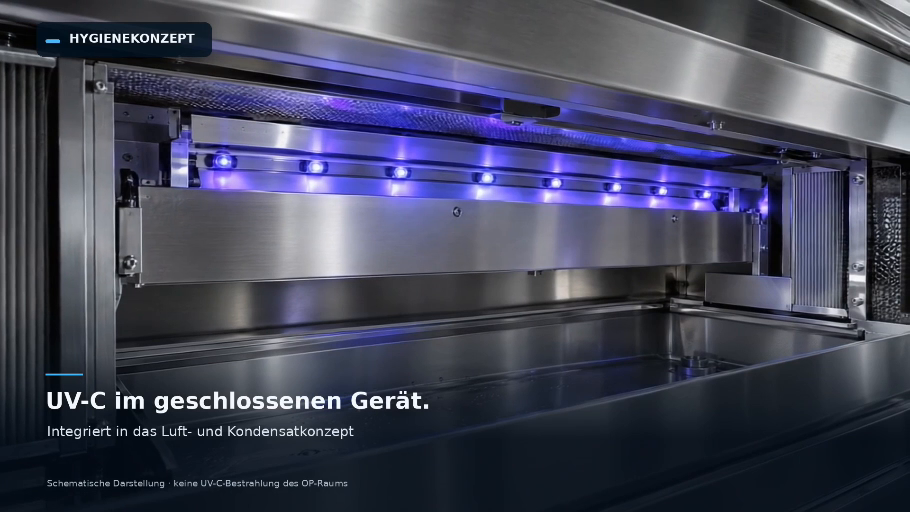
UV-C is installed and wired in the air path and condensate area. It complements the specified hygiene and maintenance measures.
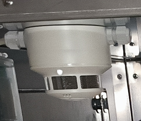
Smoke detection is provided in both side modules. System shutdown and damper operation follow the project-specific safety concept.
Each The Wall serves one operating room. Airlocks, anterooms and sterilisation areas are considered separately within the overall concept.
Rounded overall dimensions: 326 × 255 × 57 cm (W × H × D), including the 100 mm plinth and front projection. Outdoor/exhaust air, refrigerant, power and condensate connect at the top. The dimensional drawing and maintenance clearances govern installation.
Align, connect and bolt the modules together; electrical connections are plugged in. Qualified specialist contractors carry out installation, refrigerant work and commissioning.
Designed for Class Ib operating rooms. Suitability depends on design, installation, hygienic testing and operation in the specific room. Functions, airflow rates and controls are checked before handover.
The integrated remote maintenance module enables online diagnostics and reading of fault information. A secure, authorised network connection is required.
Product information: brochure dated 22 October 2026. Subject to technical changes and project-specific design.
For all our systems, we develop the equipment and controls ourselves and write the software in-house. This allows us to tailor airflow rates, temperature control and operating modes to each system concept.
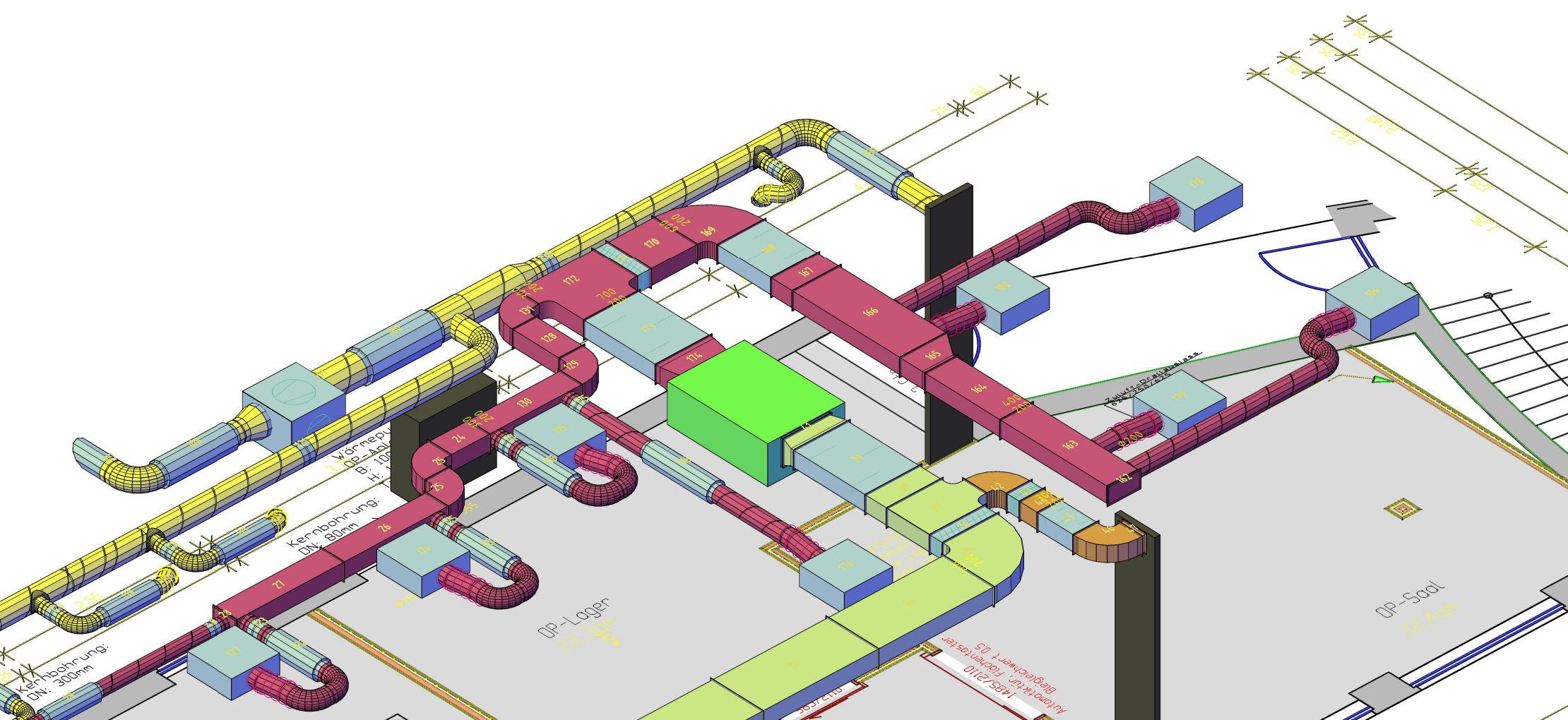
Space, air paths and installation conditions feed into the design. Planning and manufacturing work hand in hand.
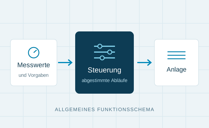
We develop the controls to suit the system, connecting measurements and setpoints with coordinated operating sequences.
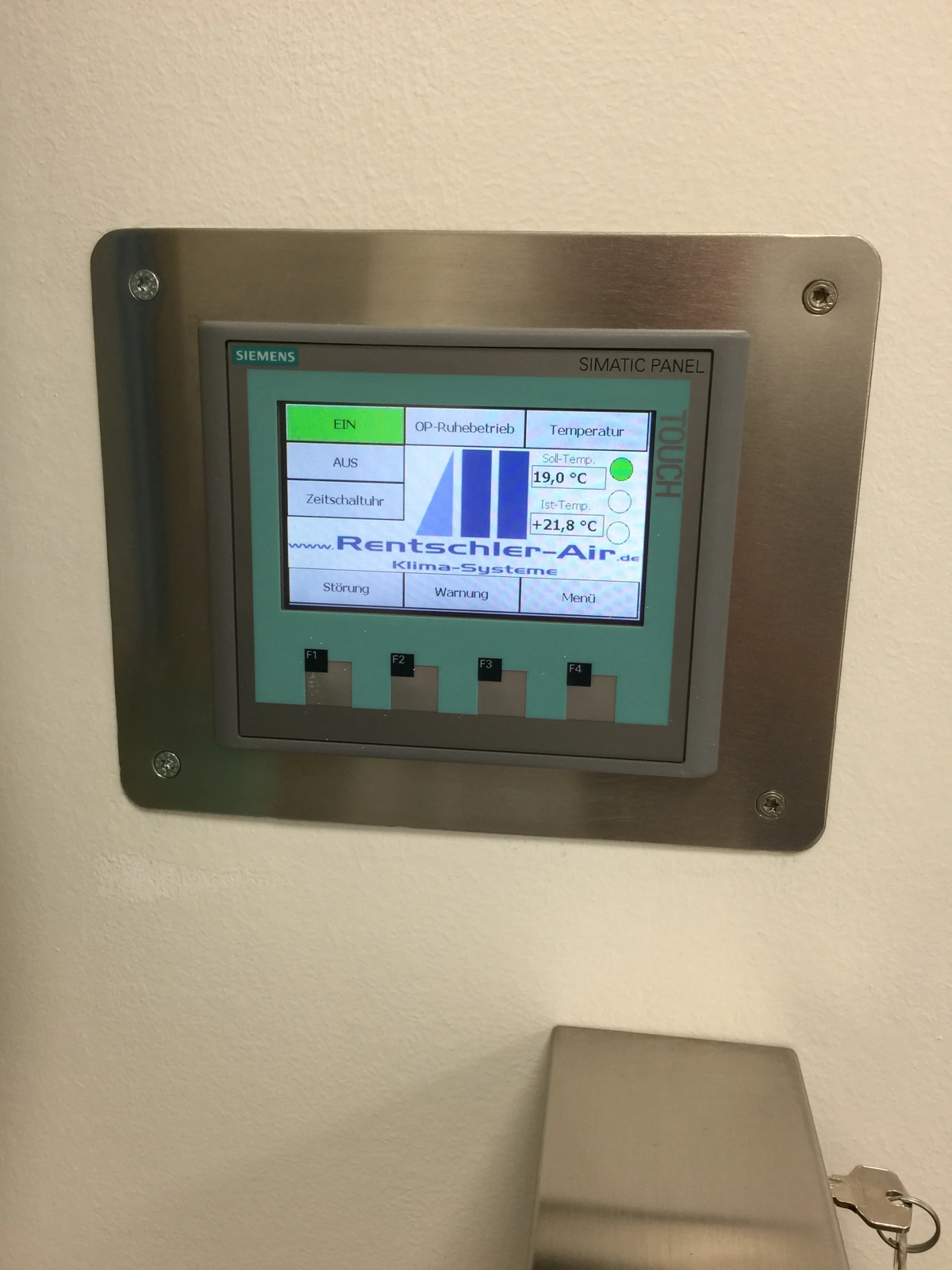
Software is developed in-house. Operation and operating modes are tailored to each system concept.