
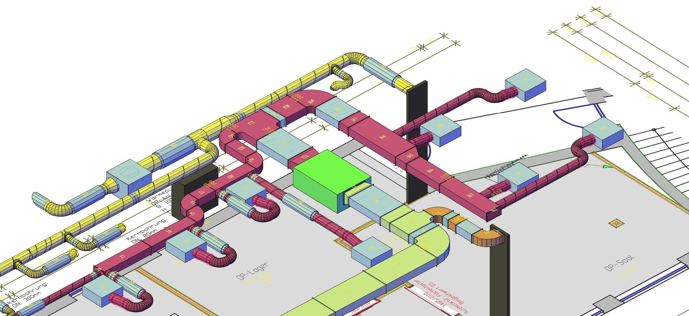
Development
Space, air paths and installation conditions feed into the design. Planning and manufacturing work hand in hand.
Heating and cooling with an integrated heat pump: the RA5000 uses the extract/exhaust air stream for heat exchange. In heating mode it absorbs heat from this air; in cooling mode it releases heat into it.
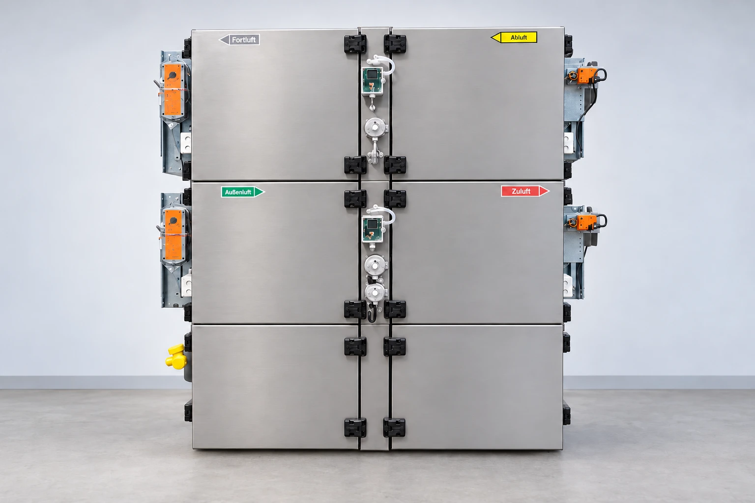
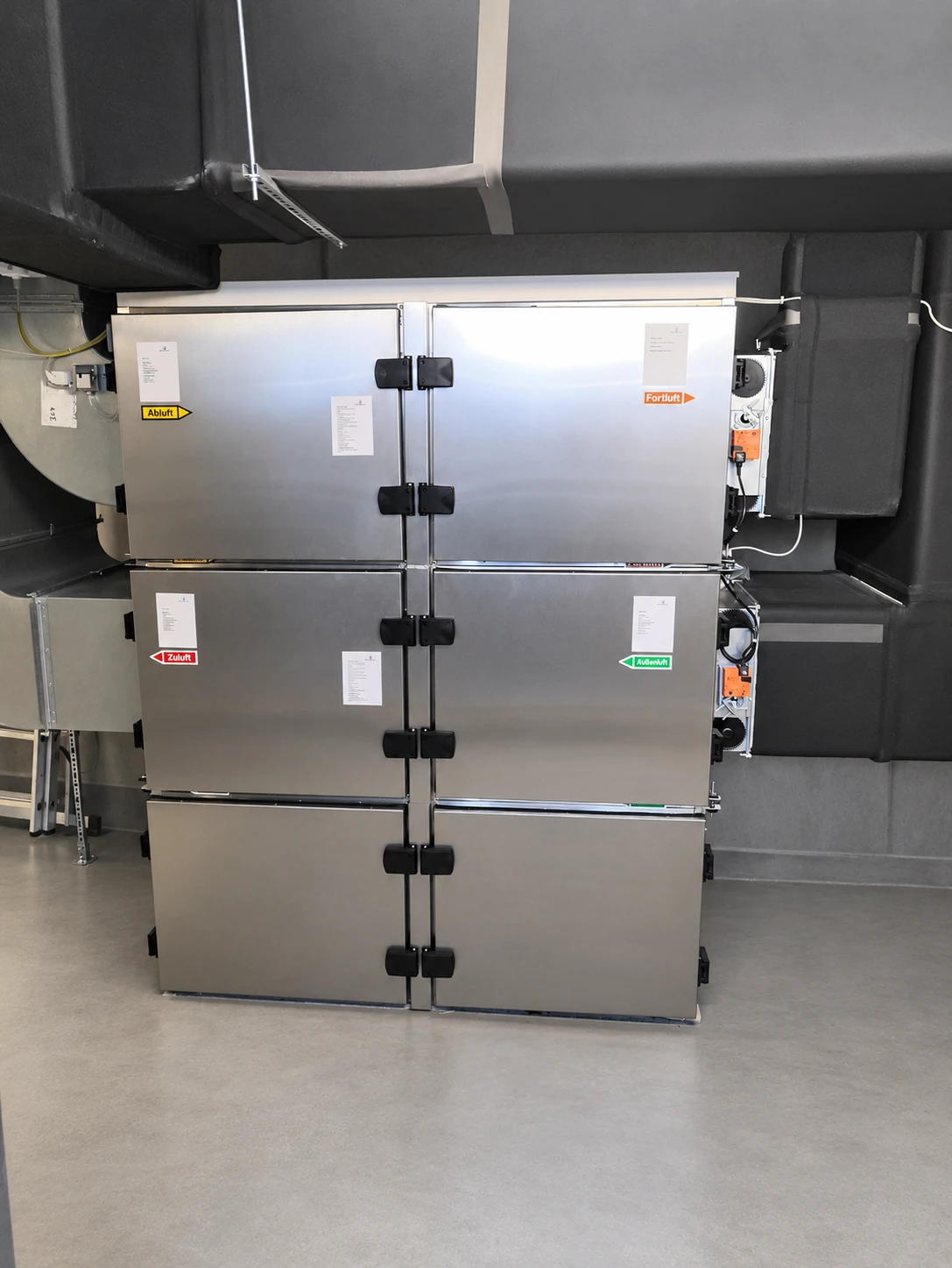
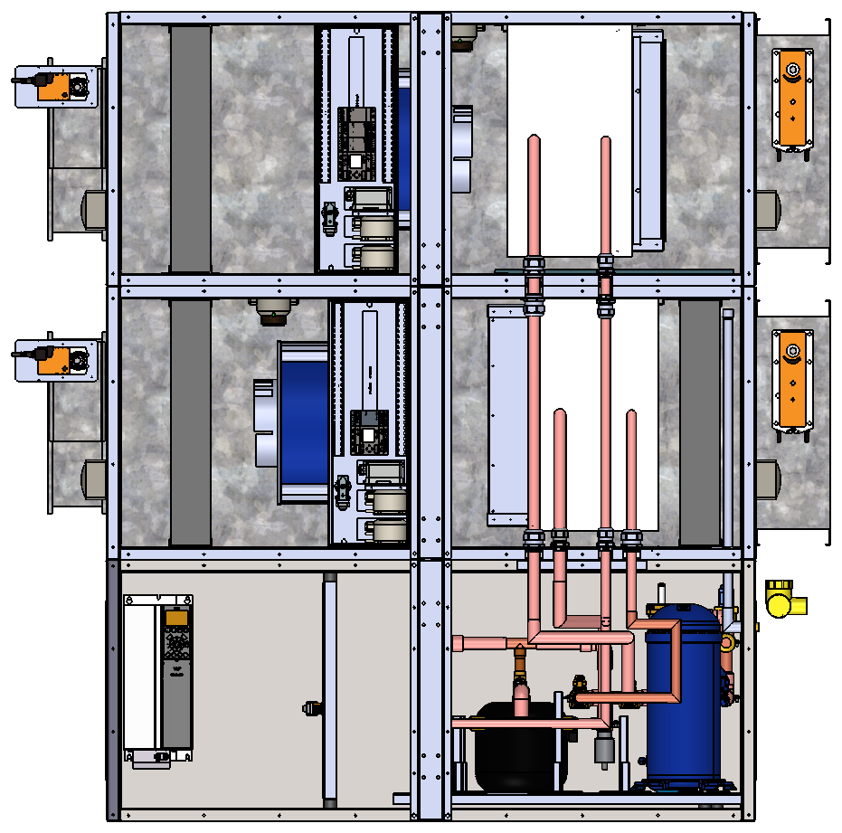
Operating principle inside the unit · No external heat pump location
The system brings heating and cooling equipment together in the cabinet unit. No separate outdoor heat pump is required.
Installation photograph with retouched surroundings. Configuration and accessibility are agreed for each project.
Explore technical views ↓The heat exchanger in the extract/exhaust air stream acts as a condenser in cooling mode and as an evaporator in heating mode. The integrated heat pump removes the need for a separate outdoor heat pump unit. This is an important planning option when an additional outdoor heat pump location is to be avoided.
Installation and planning ↓ Technical views ↓A well-designed system brings together air treatment, temperature control, air distribution and controls.
Required airflow rates and filter specifications are determined by the intended use and hygiene concept.
The integrated heat pump is part of the thermal system concept. The required capacity is determined for each project.
Supply air outlets and air routes deliver treated air to its intended location. Their arrangement must suit the use of the room.
Operating modes and controls are coordinated with airflow rates, room use and the planned pressure concept.
The vertical arrangement requires a suitable footprint and a coordinated delivery route. Alongside the unit, air routing and the clearances needed for maintenance and operation must be planned.
The exact arrangement depends on the building project. Unit configuration, pipe and duct routes and service areas are agreed before installation.
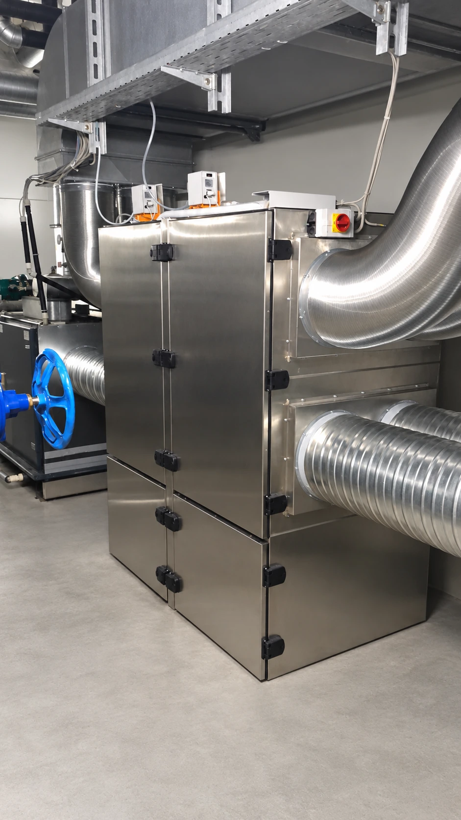
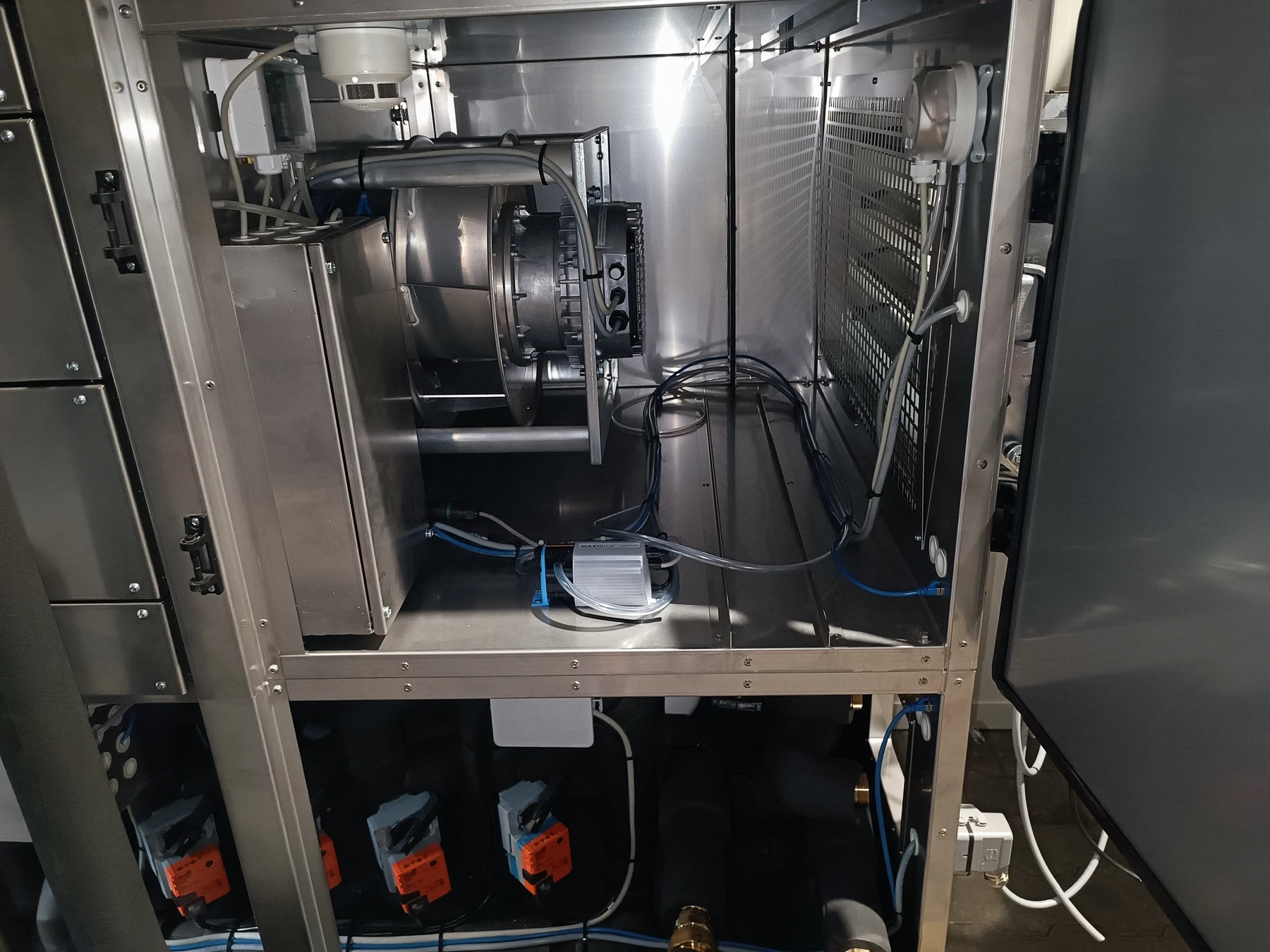
The illustrations show different configuration examples. Equipment and layout are defined for each project. Open images to enlarge.
Reliable planning considers the complete connection between the unit, building and operating room.
Supply air, extract air, outdoor air and exhaust air are routed according to the system concept. Duct sizes, routes and connection points follow from the design.
The heat pump is integrated into the cabinet unit. A separate outdoor heat pump unit is not required. This does not remove the need to plan the remaining external and building connections.
Power supply, condensate drainage and control interfaces are defined for the selected configuration and coordinated with the relevant trades.
The unit’s position, air routes and integration into the building affect its operation. The relevant requirements are considered as part of the project.
Maintenance begins with access planning. Filters, test points and components requiring maintenance must remain accessible after installation.
Keep service areas and inspection openings clear and usable after fit-out is complete.
Scope and intervals are determined by the system, its use and applicable operating requirements.
Airflow rates and relevant system functions are checked and documented during commissioning.
For maintenance and service, please use our existing online service portal.
The engineering views show how the unit sections work together – from the air paths to the integrated heat pump equipment.
Design example from the RA5000 product family. Equipment and connections are defined for each project.
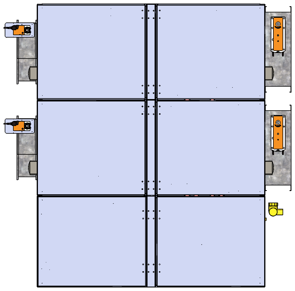
Design example from the RA5000 product family. Equipment and connections are defined for each project.
The detail view shows the heat pump assembly. Together with the controls, it is positioned in the lower section of the illustrated unit.
These views explain the operating principle. The design shown is an example configuration; connection positions, equipment and dimensions are agreed for the current project.
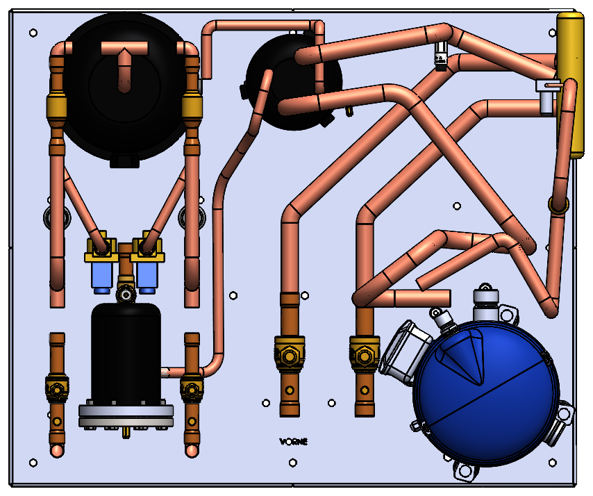
Open views to enlarge. These drawings are not binding current dimensional or installation documents.
For an initial discussion, a floor plan, intended room use, available plant space and planned air and pipe routes are helpful. For refurbishment projects, existing installations and possible installation times are also relevant.
Airflow rate, dimensions, capacity and filter specifications are determined for the project. The corresponding technical documentation then forms the basis for implementation and coordination.
Discuss your project with usSupply air outlets, LED lighting & operating room ceilings →
For all our systems, we develop the equipment and controls ourselves and write the software in-house. This allows us to tailor airflow rates, temperature control and operating modes to each system concept.
Space, air paths and installation conditions feed into the design. Planning and manufacturing work hand in hand.
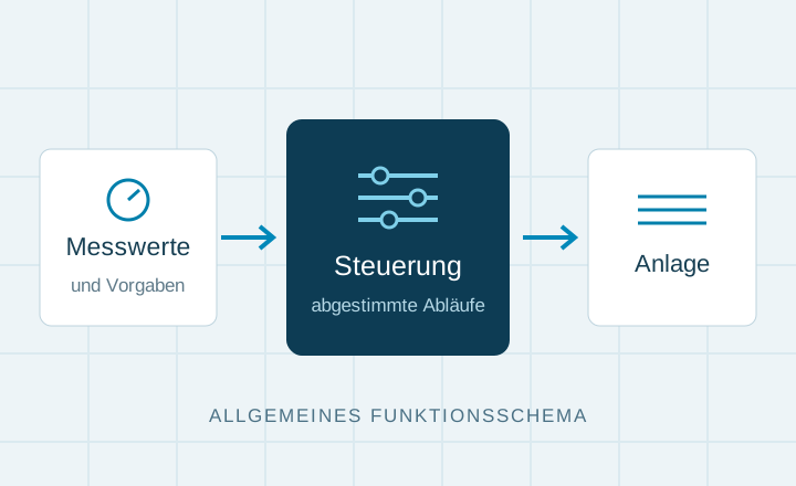
We develop the controls to suit the system, connecting measurements and setpoints with coordinated operating sequences.
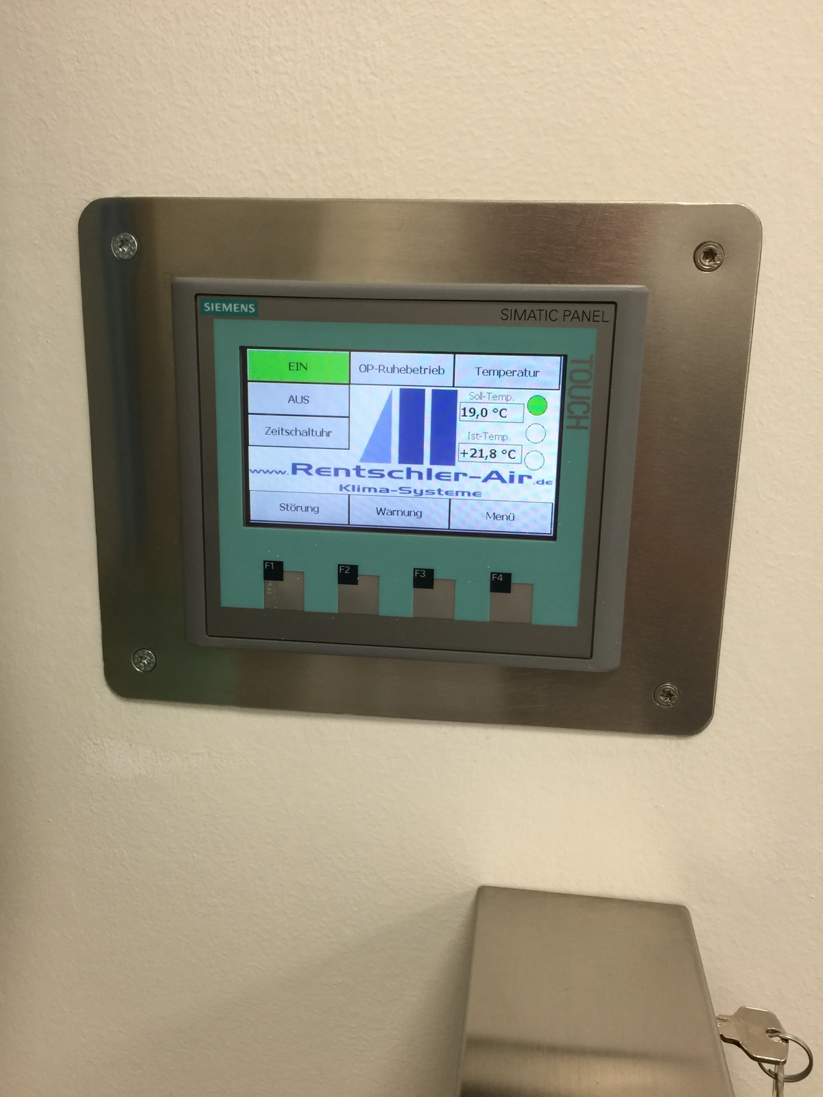
Software is developed in-house. Operation and operating modes are tailored to each system concept.